Intro to CNC Day 1
Thanks for checking out my 5-day crash course on CNC.
I’m Rob Grzesek, the founder of GRZ Software. My goal for this course is to provide you with new techniques and approaches for CNC, while keeping them as actionable and succinct as possible.
Today, we start with a look at CNC software.
Three Pieces of Software
One of the fundamental things that confuses new CNC users is the combination of software they need. It may seem like software overload but you’re going to need three programs, a CAD program, a CAM program, and a machine controller. Let’s look at each in a little more detail.
CAD Software
A CAD program is your first step in the CNC workflow. CAD, short for Computer-Aided-Design, is where you build a digital version of the parts that you intend to make. Because there are an unlimited number of parts to make, there is an (almost) unlimited number of CAD programs to choose from.
I’m an artist, I want something completely free-form
If you care more about achieving the perfect organic shape, and don’t need perfect dimensional accuracy, then you might want one of the more organic CAD programs. These use sculpting metaphors to make a part rather than traditional drafting techniques. Take a look at:
Silo3d https://www.nevercenter.com/silo/ ($159)
Zbrush https://www.pixologic.com/zbrush/ ($699)
Mudbox https://www.autodesk.com/Mudbox ($799)
Blender https://www.blender.org (Free)
These are going to be great for anything from woodworking, to jewelry, to action figures. They all have a very different way of working so it’s worth trying a number of them to see what fits you style better.
I want to make free form parts but I need some accuracy
The programs above are for a select group of people- users that love a complete lack of structure so that they can be free to do anything. This freedom typically comes with a significant cost, it’s very difficult to make things that are dimensionally accurate. For example, if you need to make a canopy for an R/C airplane or the neck of a guitar, then you want to ability to make nice compound curves but you also need it to physically fit into the rest of the project.
If this sounds like you then the programs below would be a great starting point.
Rhino https://www.rhino3d.com (About $1000)
Viacad https://www.punchcad.com/p-9-viacad-2d3d-v8.aspx (About $100)
Sketchup https://www.sketchup.com (Free or $500)
I want to make parts that even German engineers will call beautiful
When you want absolute precision and a clean workflow then there is no substitute for a parametric CAD program. The “parametric” description come from the way that shapes are defined. Rough sketches and operations like extrusions or cuts are defined first, then the exact dimensions and sizes are added and the part updates to the new size.
The power of this approach is that parts of the design that were drawn first can be changed and the whole part will update (mostly) automatically. Programs like Rhino and Viacad would require you to redraw the part from the change forward. This ability to adapt to changes is why you will rarely find any manufacturer using anything but a parametric CAD program for a production part.
Alibre https://www.alibre.com ($199 to about $1000)
Solidworks https://www.solidworks.com (About $3500 + annual maintenance)
OnShape https://www.onshape.com (Free to $1500 per year)
All three programs are similar. Alibre can do almost everything that Solidworks can so it’s worth a look.
The high price of Solidworks and OnShape will scare many people. If you’re going to live in a CAD program every day then the amortized cost of the program isn’t that bad if it makes you more productive. There are sometimes leasing deals available that make the cost of the software much more affordable by including the maintenance and the program cost into a single monthly payment over a period of several years.
I don’t know what CAD I want, where do I begin?
If you just want to get started in the next few minutes without downloading anything or speaking to any salespeople, then you should check out the two CAD programs below. They are part of a new breed of programs that run completely in the browser and in the cloud- there is nothing you need to download. The only requirement is a modern browser like Chrome or Firefox that can support the 3D features they require.
Tinkercad https://www.tinkercad.com ($10/month and up)
Don’t be fooled by the simple nature of this program, it’s a very capable CAD program.
OK, I’ve got the CAD, now what?
If you were going to work with a machine shop then you could stop now and just give them a copy of your CAD file; it contains all of the relevant dimensions of the part so that an experienced machinist would be able to make it. In this case, you’re the machinist so you’ll need another program that can take the CAD file and figure out how a cutter needs to move to be able to machine it. For that, we need a CAM program.
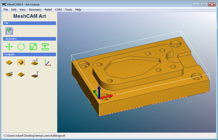
CAM Software
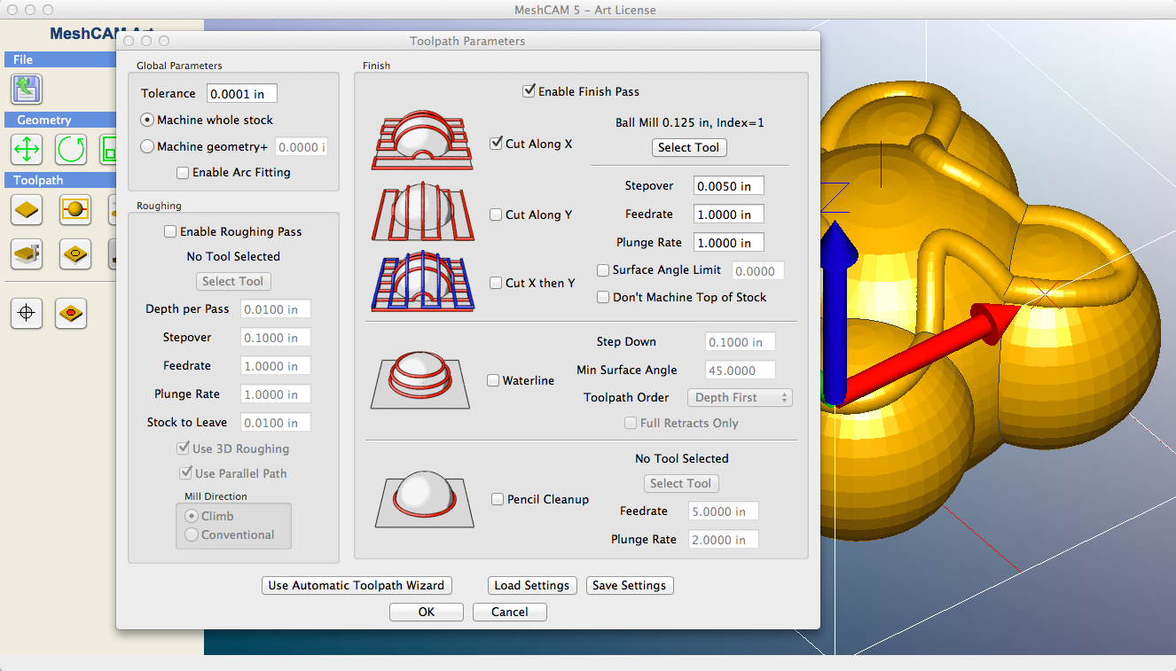
CAM software, short for Computer-Aided Manufacturing, can look at a CAD file and figure out how your mill or router needs to move to cut out the part.
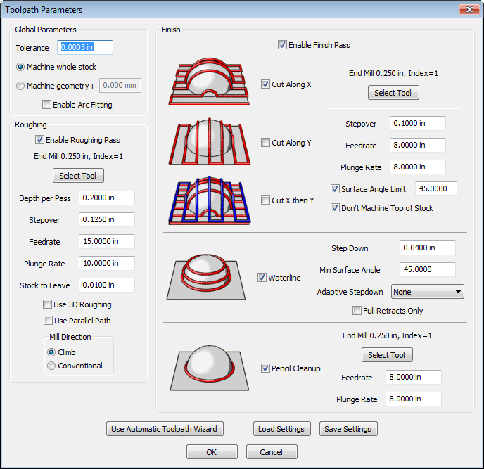
The exact path of the mill, called a toolpath, used to cut out your part depends on a number of factors- the kinds of cutters that you use, the kind of stock that you are cutting from, the quality of finish that you need, and the amount of time that you’re willing to wait for a part to be done. The CAM software takes these inputs and does a ton of math (it could literally be billions of calculations) and outputs a toolpath to be loaded into your CNC machine.
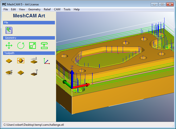
Your CAM program will output a file called G-code. G-code is a standard file format that most mills and routers can understand. It contains all of the information your machine needs to know where and how fast to move to cut out your part.
I’m going to be honest here and say that I’m biased toward MeshCAM (https://www.grzsoftware.com ) for CAM software because I’ve spent the last eight years writing it. It’s got a totally free 15-day trial so you check it out if you’re looking for CAM software.
Machine Controller
Without one more piece of software, your mill or router is just a manual machine with motors connected to it but it won’t do much. A machine controller is used to control those motors and coordinate their movement based on the g-code from your CAM software.
If you’re lucky enough to have a big machine like a Haas ( https://www.haascnc.com ) or a Mori Seiki ( https://www.moriseiki.com) then your machine came with a computer with a proprietary machine controller built in and you’re ready to run.
If you bought a lower-cost machine, or are retrofitting an older machine, then you probably have a standard PC connected to your machine running either Mach 3 (https://www.machsupport.com ) or EMC2/LinuxCNC ( https://www.linuxcnc.org ). The two programs are similar with the exception that Mach 3 is a Windows program and EMC2 runs on Linux. Both are exceptional and both have big followings online.
All machines, even if they have the same machine controller, are built and configured differently. While g-code is a standard, some machines will require slightly different g-code formatting or a different setup. All good CAM programs support multiple post processors to correct for these differences. The post processor is responsible for taking the instructions from the CAM software and making whatever changes are required for your specific machine model.
Most CAM programs will come with a dozen or more post-processors built-in; unless your machine is odd, your CAM program is likely to support it out-of-the-box.
That seems way too complicated
I have to agree, three programs to make a part seems like overkill. The more you dig into the process, the more you’re going to see the genius of it. The three programs each have a specific purpose and each can be swapped out for something that fits you and the way you think.
I promise that the three-program workflow will become automatic for you after the first week of using it.
Next…
From here we’ll get into topics of more substance. Until then, try a couple of CAD programs and see if you can find one that fits your way of thinking.
Tomorrow, we’ll be delving into CNC cutters and materials.
If you have any questions in the meantime, please hit the reply button and drop me a line. I will respond personally to every email.
And if you’re ahead of the curve and want to get started, feel free to learn more about MeshCAM here.
Until tomorrow,
Rob Grzesek
Founder, GRZ Software
Intro to CNC Day 2: Cutters and Materials
Hi- Rob from GRZ Software here. You signed up to get a CNC course via email from me. If you’d like to unsubscribe at any time, there’s a link at the bottom of this email.
Yesterday you learned about CNC software. Today we’re going to dive into CNC cutters and materials.
Cutters
End mills are the actual cutting device on a CNC machine. Literally thousands of them are available in every shape and size imaginable. If you don’t know much about them then your eyes can glaze over when looking at a catalog. If you know just a couple of things then it’s easy to break this wall of cutters down into something more manageable.
Cutter Shape
The most important cutter characteristic is the shape and you’ll find that lots of shapes are available. Unless you have good reason to do otherwise, you can ignore all but two: the flat endmill and the ball mill.
Flat Endmills
As the name suggests, flat endmills are, well, flat. More specifically, the overall shape is cylindrical and the cutting end is flat. As you might imagine, the flat end of the cutter makes it easy to cut surfaces that are horizontal with the bottom of the tool, or vertical, which is the side of the tool (also called the flank). Any angle other than 0 or 90 becomes more problematic- a flat endmill simply cannot do it well.
Ball-End Mills
Ball-End Mills, or Ballmills, replace the flat bottom with half a sphere. The benefit here is that you can cut a surface with complex curves and get a very good finish. If you plan on cutting parts that have non-flat surfaces then ballmills will be part of your toolbox.
Flute Length
Another important characteristic of is the *flute length*, which is the length of the part of the endmill that cuts. In an ideal world the flutes would be very long so that you could cut deep into the stock without any part of the mill getting in the way. Unfortunately this doesn’t work in the real world.
The longer the flute get, the more the cutter will bend when it is under load. This bending has two big drawbacks- it makes your parts less accurate because the tip of the cutter is not where the mill expects it to be. The second, and more important problem, is that the bending leads to the cutters breaking. This wastes time and money so it’s something to worry about.
Generally speaking, you can get “normal” cutters that have a flute length that is three times the diameter. For example, a 1/8” diameter cutter might have a flute length of 3/8”. There are so-called *stub-length* cutters that have a much shorter flute length to reduce flex. There are also extra-long cutters that have a longer flute length but they must be treated with care because they are more prone to breaking.
Tapered Endmills
A Ballmill or Endmill is also available in one more configuration, with tapered flutes. A tapered cutter had a triangular shape- the sides are angled at somewhere between .5 and 15 degrees. This means that the flute diameter gets larger higher up on the cutter. The big benefit here is that you can get much longer flute lengths in a tapered cutter because the flutes are much more rigid.
The tradeoff for the extended reach is that a tapered cutter is unable to cut a vertical surface because the cutter itself has no vertical flutes. If your part has no vertical surfaces then you’re fine. If it does, then you have to accept them being cut with a slight taper or you have to do a second cutting operation with a straight cutter get them totally vertical.
In spite of the limitations, a tapered ball mill is one of my favorite cutters to use.
Number of Flutes
A flute is the actual cutting surface of a cutter and every cutter has one or more flutes. How you decide between a 2 or 4-flute cutter requires a little more explanation.
When your stock is being machined, it is turned into a bunch of chips as the cutter turns. These chips need to be moved out of the way to make room for more to be created. If they remain trapped in the flutes then you will generate more heat and/or break the cutter. Normally the chips travel up the flutes and are ejected out the top.
As you add more flutes to a cutter, the area for the chips to travel up is reduced so you have to be very careful to make sure that they are not getting stuck in the area being machined.
There is no magic solution where you can guarantee good chip removal, it depends completely on the material you’re machining, the shape you’re machining, and the speed that you’re machining it. Until you have gained more experience you should buy cutters that have 2-4 flutes.
My Favorite Vendors
eBay
Amazon
Harvey Tool
Discount Tool
Micro 100
Enco
Precise Bits
Stock Materials
The other big consumable in CNC machining is the stock materials. If you’re looking into CNC machining then you probably already have a few materials in mind. Rather than an exhaustive list I’ll just go over some of the big ones and try to cover a few that may be unfamiliar.
MDF- Everyone starts with MDF, or medium-density-fiberboard. You can get it anywhere and it machines pretty well. You cannot do really detailed work with MDF because small parts have a tendency to shear off very easily. It has the benefit of being a cheap material and it’s good for things like pattern making.
Delrin/Acetal - Acetal, or Delrin if you buy the Du Pont version, is a moderately expensive plastic that machines extremely well. Unlike softer plastics that melt and gum-up the cutter (remember the thing about chip removal?), Acetal machines very cleanly. Due to cost, it isn’t practical to machine large items with it.
ABS - ABS is one of the most common plastics used today. It machines fairly well, although you do have to make sure to don’t build up too much heat and cause it to melt. Once you get the cutting speeds figured out for your application you’ll probably have very good luck with it. It’s also much cheaper than Acetal.
Machinable Wax - Machinable wax is usually used for quickly testing toolpaths that will take a long time to run on much harder or to make sure there are no mistakes before committing to more expensive materials. It is designed to be machined easily and not load up cutters with chips. Wax is also used by jewelers to make patterns from which a mold can be made.
High Density Foams - You may not be familiar with high density polyurethane foams but they are popular in the sign making industry and for things like movie props and sets. The density can range from 10 to 30 pounds per cubic foot so they can be fairly durable. High density foams machine very well but they create a gritty dust that goes everywhere; it will take days to get it off of you. In spite of this, they offer a good way to create large parts that machine well and are lighter than other options like MDF.
Tooling Board - Polyurethane tooling board is a close cousin of the foams mentioned above with a few significant differences- they don’t create the same dust and they are much higher density. They can range from 20 to 50 pounds per cubic foot and have no “grain”. They machine really well and are capable of holding incredible surface detail. Tooling boards are popular for pattern making, making product mockups, and for testing toolpaths before committing to a more expensive or difficult to machine material. This is one of my favorite materials to machine; in particular I like RenShape 440 ( https://www.freemansupply.com/products/machinable-media/renshape-modeling-and-styling-boards/renshape-440-styling-board ) .
Brass/Bronze - Brass and bronze tend to machine very well. They are not the strongest metal but if I have a part that needs to be stronger than plastic I try to use brass.
Aluminum / Steel / Etc. - There are lots of other materials to machine but they are almost all more difficult to machine than the ones listed above. If you’re new to CNC then stick to the ones above at the beginning.
My Favorite Vendors
Machinable Wax - https://www.machinablewax.com/
Freeman Supply - https://www.freemansupply.com/ - Foams and tooling boards
McMaster Carr - https://mcmaster.com - Plastic, metal, and tooling board in smaller quantities.
Online Metals - https://www.onlinemetals.com
eBay - Good deals of chunks of plastic.
Next up
This is the last “What to buy” email for a while. I assume that you have a machine already so if you pick up some software and materials then you’ll be ready for some projects.
Next up, we’ll learn about CNC speeds and feeds.
If you’re interested in learning more about CNC software, you don’t have to wait for the rest of this course to get started- check out a free trial of MeshCAM at https://www.grzsoftware.com/download/
Until tomorrow,
Rob Grzesek
Founder, GRZ Software
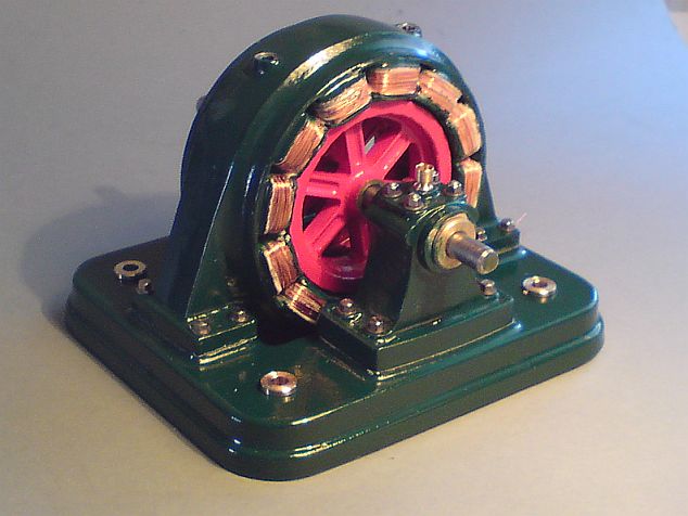
Intro to CNC Day 3: A Simple Project
Hi- Rob from GRZ Software here. You signed up to get a CNC course via email from me. If you’d like to unsubscribe at any time, there’s a link at the bottom of this email.
The last two emails went through a list of the materials and software that you need to buy for CNC machining. Hopefully you’re on your way to being well stocked and ready for a simple project. This is the kind of thing that I prefer to do with a video- hopefully it will be easier to watch than to read

Want to try this project at home?
Here’s what you need:
1) Download the STL file for the project at: https://www.grzsoftware.com/intro/rosette.stl
2) Download a trial version of MeshCAM from https://www.grzsoftware.com/download/
3) Get some stock and a 1/8” ball mill and follow along.
Next…
As you watch the video above it’s likely that you’ll have a number of questions. The next few emails will address a number of the confusing points in more detail. In the mean time, don’t hesitate to get in touch if you want answers now.
Regards,
Rob Grzesek Founder, GRZ Software https://www.grzsoftware.com
Intro to CNC Day 4: CNC - Speeds and Feeds
Hi- Rob from GRZ Software here. You signed up to get a CNC course via email from me. If you’d like to unsubscribe at any time, there’s a link at the bottom of this email.
Yesterday you learned CNC cutters and materials. Today we’re going to dive into CNC speeds and feeds.
One of the most common topics for questions I get is, “How do I pick a Feedrate?” It’s a good question and it doesn’t have a single answer for everyone.
In fact, if you watched the project video then you’ll notice that I just glossed over the feedrate selection with a comment about, “picking something appropriate for my machine”. Here’s a little more info about how you might do that.
Speeds vs Feeds
Before we go further, here’s a quick clarification of the two terms that are relevant here:
Speeds refers to the rotational speed of the cutter in RPM, or revolutions-per-minute.
Feeds or Feedrate refers to the speed that your cutter is moving through the stock. This is usually measured in units like inches -per-minute or MM-per-minute.
Why Speeds and Feeds Matter
Picking good values for the feedrate and speed are critical to effective CNC machining for a number of reasons:
- Bad values can lead to broken cutters and wasted stock material
- Bad values can lead to loss of accuracy
- Bad values can lead to a poor surface finish
- Bad values can make a toolpath take much longer to run than it needs to.
Picking the correct values can make all of these problems go away.
But what’s the correct value?
The Math Approach
I’m going to warn you right now that you should skip this section- nobody really wants to know this. You’ve been warned.
There have been countless academic papers from PhD’s that try to characterize the physics behind the cutting action of an endmill. Over time, a consensus has developed about the most simple equations that should define your speeds and feeds. Wikipedia has a good writeup at https://en.wikipedia.org/wiki/Speeds_and_feeds but it’s mind-numbing- and this is coming from an engineer that loves talking about CNC.
There are two factors that define the speed and feed- SFM and chipload.
SFM or surface feet per minute is the speed that the flute moves through the material. If you were whittling a piece of wood with a pocket knife then the SFM would be analogous to the speed that you drag the knife down the edge of the wood.
Each stock material has an ideal SFM value that depends on its physical properties. These SFM values can be found in a number of places, including the Wikipedia article referenced above. Based on a given SFM and the diameter of your cutter, you can figure out the speed in RPM that your cutter should turn using the following equation:
RPM = (SFM *12) / (PI * DIAMETER)
If you accept some error and assume that PI is equal to 3 then you can simplify that to:
RPM = (SFM * 4) / (DIAMETER)
For example, a .25” emdmill cutting brass with a SFM of 300 (from Wikipedia) would be:
RPM = (300*4)/.25 = 4800 RPM
Now we can look at the feedrate which is based on another material-defined value, the chip load.
Chip load is simply defied as the thickness of the chip that each flute should cut.
Back to the whittling example, if SFM is the speed that you move the knife along a piece of wood, the chip load is the depth of the knife in the wood on each stroke.
While the SFM is defined by the type of material, the chipload is defined by the cutter manufacturer based on the material you are cutting.
Feedrate = RPM * NUMBER_OF_FLUTES * CHIP_LOAD
Back to our brass example with a chipload of .002 for a Harvey Tool cutter,
Feedrate = 4800*4*.002 = 38.4 inches per minute.
Because the desired chipload depends on the type of cutter you’re using so you may want to get it directly from your supplier if you’re going to aggressively push the limits. If not, you can get a table herehttps://www.harveytool.com/cms/GeneralMachiningGuidelines_17.aspx and it should work fine for similar tools.
So for brass we have a speed of 4800 RPM and a feedrate of 38.4 inches/minute. What if your machine can’t go above 20 inches/minute? You can adjust both down proportionately to 2500 RPM at 20 inches/minute and everything should be OK.
Going with your gut
If you smartly skipped the math section then it’s likely that you plan on doing what we all did at some point- start with a seemingly reasonable number and tweak it up and down until is seems “more correct”. If you’re going to do this then here are a few tips:
Don’t assume that you should just crank up the RPM to the maximum and go. If you’re cutting metal or plastic and generating dust instead of chips then you may need to move the RPM down or move the feedrate up.
Likewise, if you’re cutting plastic and it’s melting around the cutter then you may need to move the RPM down or the feedrate up.
If your machine is on the smaller side and vibrating while cutting then you may need to slow the feedrate down or move the RPM up.
This method works but it won’t always help you get to the best solution even if it does get you going quickly.
Going with the “Sure Thing”
So far we have two options, do a bunch of painful math or do some trial and error. Here’s my best option for you: get a copy of G-Wizard from CNC Cookbook.
Bob, the developer, baked all of the math above and a bunch of tables of data for various material types into a program that just gives you the bottom line numbers. It also is able to take additional parameters into consideration to do thing like correcting for the size of your machine to telling you how much flex your tool will have to help you eliminate errors in the finished parts.
I love this program; it’s helped me a ton.
Even if you don’t buy a copy, take advantage of the trial period to build a list of speeds and feeds for all of your favorite cutters and materials.
Check it out here: https://www.grzsoftware.com/intro/gwizard/
Conclusion
If it makes you feel better, that was just as painful to write as it was to read. It is such an important topic that it’s worth the pain to get through it. Getting good results from CNC depends on getting familiar with this topic.
Now that you understand about CNC speeds and feeds, tomorrow’s installment will dive into how to pick a program zero.
Until then,
Rob Grzesek
Founder, GRZ Software
P.S. If you’d like to get started with CNC software, you don’t have to wait for the rest of this course to do it; check out our free trial.
Intro to CNC Day 5: How To Pick A Program Zero
Hi- Rob from GRZ Software here. You signed up to get a CNC course via email from me. If you’d like to unsubscribe at any time, there’s a link at the bottom of this email.
Today, we’re going to discuss how to pick a program zero.
Here’s another thing that went by very quickly in the first project video - picking a program zero.
When you’re just starting you can pick just about anything and the part will probably come out just fine. As you become more proficient, you’ll want to set the program zero with more care to improve you productivity and accuracy.
The purpose of the zero
At a basic level, the program zero tells the mill where to find the stock on it’s table. Since the mill table is generally much bigger than the stock you are cutting the mill must be told where you’ve put the stock. Without this registration process, there is very little chance that anything would line up.
The program zero also gives the CAM software a single reference point for the toolpath. On a mathematical level, the CAM program can accept any arbitrary zero point, it’s just an offset in space and one is as good as another. For you, the machinist, the program zero must be something you can locate with the mill; if the point cannot be located then you are probably going to have a lot of problems.
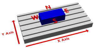
A quick definition
It’s difficult to write clearly about sizes and edges when we talk about the location of the zero. MeshCAM uses the compass layout- north, south, east, and west, to describe the location. This can be seen more clearly in the image below:
Location, location, location
Imagine, for instance, a zero that was 10 inches to the left of the bottom corner of the stock. While this is a point that does exist, it’s in empty space so you have very little chance of accurately finding it.
By contrast, if you were to pick a corner of the stock then you have three planes/sides that you can touch the tool off of, the top, side, and front.
While this zero may take a few minutes for a new machinist to locate, it’s not hard to do if you’re patient.
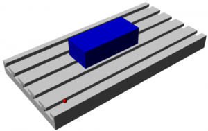
The best default position
If I had to give you one default position to pick it would be the top of the stock, in the lower left-hand corner, the southwest corner in MeshCAM terminology. In general, this is what I use 90% of the time; it works well, it’s easy to locate and it keeps all of the X and Y toolpath coordinates as positive numbers. Z coordinates will be negative when you’re cutting into the stock and any positive Z number should be in the air. The only time the Top Southwest position may give you trouble is when you need to change tools.
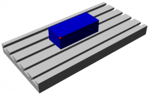
What about tool changes?
All of the coordinates in the gcode file tell the mill where to move the tip of your tool. If you change tools in the middle of a machining job then you need to reset the Z value of the zero since the two tools are not likely to be exactly the same length. The point you pick for a zero must be available any time you need to do a tool change and reset the tool length. If the point initially used has been machined away by the roughing operation then you’ve lost the ability to set your tool length. Image that you’ve set the zero on the top, southwest corner as seen below:
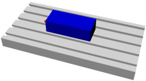
Now you’ve finishing roughing and you’d like to use a different tool for the finishing. You need to touch off that corner again except that it isn’t there:
In many machine controllers it is possible to preconfigure everything so that a tool change doesn’t require a rezero. This option requires very accurate tool holders that keep the length constant and a lot of effort on your part to measure and input all of the length data before machining begins. In my experience, very few people do this.
The one saving grace here is that you really only need to recover the Z value and you might be able to recover that from a different section of the stock or as an offset from the table, if you knew the original thickness of the stock with sufficient accuracy.
So where should the zero be?
Well, there’s no single answer but none of them are very difficult. Here are a couple of things to keep in mind each time:
- Will the zero be there when you need to change a tool?
- If not, is the stock and machine flat enough that you can locate a different point and apply an offset?
- Maybe it’s easier to just machine the whole thing with a single tool and not worry about a rezero for a tool change. This is usually not the right answer but I’ll admit to doing it when I just want to get something done quickly.
Those three criterion are good enough most of the time and most users will never have to go beyond that.
Tomorrow, in the final installment of this course, we’ll take an in-depth look at choosing a stepover.
You won’t want to miss it,
Rob Grzesek
Founder, GRZ Software
Intro to CNC Day 6: Choosing A Stepover
Hi- Rob from GRZ Software here. You signed up to get a CNC course via email from me. If you’d like to unsubscribe at any time, there’s a link at the bottom of this email.
Today we’re going to take a look at choosing a stepover value.
One of the fundamental parameters of any CNC machining, and 3D machining in particular, is the stepover. It is not a stretch to say that it is the single most important parameter in determining the quality of the finished parts you will produce. A machinist can pick a value by feel, based on previous experience, or do the math and calculate the exact value that will give them the finish required. New users generally don’t have the experience and don’t know the math so it takes a while to get an intuitive understanding of of the stepover parameter.
This email focuses mostly on 3D toolpaths so we’ll be assuming the use of a ball mill. Once you understand the basic concepts it’s easy to apply them to flat end mills and bull mills. We’ll try to build to some rules of thumb rather than derive equations that most users won’t be interested in.
Definition of Stepover
Almost all CNC toolpaths are based on the concept of one toolpath being offset from another by some distance; this offset distance is generally called the stepover. Most CAM software, MeshCAM included, uses a couple toolpath styles in particular with these offsets- the raster toolpath (sometimes called a zig-zag toolpath) and a contour offset.


Adjacent sections of the toolpaths above are separated by the stepover value chosen by the user.
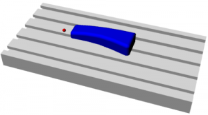
Scalloping
The pictures above show how a toolpath is arranged from above but a side view clearly shows the primary side effect of your stepover choice- scalloping.

The area in red is the part of the stock leftover on the part in between the toolpath offsets. It’s important to understand that these are not good; they are not in the CAD and may need to be removed after machining by sanding or polishing. CNC machinists are almost always trying to reduce the scalloping as much as possible and many man-years of effort have been spent trying to develop toolpath algorithms that minimize them.
Scallop vs. Stepover
A moment spent looking at the image above illustrates at connection between scallop height and the stepover value- increase one and the other increases as well. In the images below we’ll use a stepover equal to 1/10, 1/5, and 1/3 of the tool diameter to show this correlation. To put real numbers on this, that would be equavalent to a .012, .025, and .042” stepover for a .125” ball mill.


As you can see, the change in quality is so dramatic that you might be tempted to always use the smallest stepover possible.
Speed vs Quality
It shouldn’t be surprising that you’ll have to give something up if you want to use a really small stepover. In this case you’ll trade time for quality- you give up machining speed to use a small stepover or give up quality if you want a quick machining time. This is easy to understand when you consider that the total length of a toolpath will approximately double if you cut the stepover in half. The question is, “Will cutting the stepover in half double the quality of my part?”
The Sweet Spot
It turns out that there is a point of diminishing returns in the time/quality tradeoff. Below is a graph of scallop height vs stepover that illustrates the effect. The graph has been normalized to a tool diameter of 1.0 so it’s easy to scale it to any tool you happen to be using. (Click on it to see a bigger version)
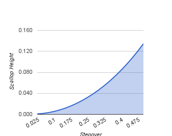
The important thing to note is the shape of the graph- it tends to flatten out when the stepover goes below about one eighth of the diameter. This means that when you go below this point you’re going to take more time to machine without a proportional gain in finish quality. If you’re machining a steel injection mold then it may still be worth it but you really need to be sure before doing that.
Scallop vs. Tool Diameter
Here’s the other thing we can glean from the math behind the chart above- for a given stepover, a larger tool will give you a smaller scallop. This means that you can get a better finish “for free” if you can use a larger tool. Obviously, this only works if a bigger tool will fit into all of the parts of your geometry but this is one of the few “win-win” things we can do get better results if it does work for your geometry.


Keep the Material in Mind
Before you figure out what stepover you need to get a .0001” scallop, think about what you are going to machine- wood, tooling board, aluminum, steel, etc. I can tell you that in many cases you can do 10 minutes of sanding on a wood part to get a finish that would have taken you an extra hour or two to get straight from the mill. Likewise, tooling board like Renshape can be hand finished quickly enough that it may not be worth doubling the machining time to get a better finish. If you’re cutting steel or other hard materials then it’s probably worth letting the mill do more of the hard work.
The second characteristic of the material to consider is what kind of detail it can hold. MDF will not hold features in the .01” range but metal will. If your material cannot hold a detail that is smaller than your scallop height then you do not need to reduce the stepover; doing so will only waste your time without producing a better finish.
Keep the CNC Machine in Mind
It may be a poor craftsman that blames his tools but we do have to be realistic about the nature of our equipment. In particular, how long do you trust your mill or router to run trouble-free? I started out with a small table-top mill that, while very good, could not be trusted to run for hours without missing a step or hiccuping in some way that gouged a part I had waited half a day to get. If you have a machine like this then it’s worth thinking about the picking the maximum stepover based more on machining time than finish.
Rules of Thumb
That was a nice bunch of pictures but you may still be left with the question, “So what stepover do I use?” Here are a few suggestions:
- The stepover should be between 1/3 and 1/10 of the tool diameter
- Use a larger stepover, in the 1/5 to 1/3 range, for soft materials that cannot hold detail well
- Use a smaller stepover, in the 1/5 to 1/10 range, for hard materials or materials that can hold significant detail like metal and jewelers wax
- Use the largest tool that will allow you to machine your geometry
Once you have a few projects complete you can adjust the guidelines above to suit you materials and machine.
That wraps up my 5-day crash course on an intro to CNC.
If you’re interested in learning more about CNC software, be sure to check out our free trial.
I’ll be in touch in the coming weeks as we discover and develop insights into the world of CNC. And as always, please let me know if you have any questions by replying to this email.
Until then,
Rob Grzesek
Founder, GRZ Software