With all of the powerful CAD/CAM programs out there, one of the most common tasks is the conversion from DXF to g code. Frequently there is no need to pocket or face the stock- just cut out the objects in the file from flat stock. Given this simple task, many CAM programs look like overkill. Can we make this common 2D task easier with 3D CAM software? Yes we can.
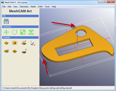
We’ll use the part below to show how we can do a DXF to g code conversion with minimal effort:
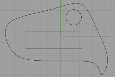
This files contains a good combination of arcs, line segments and bezier curves. Also, these is nesting where the rectangle and circle are within the outline curve. MeshCAM will have no problem finding this hierarchy and generating a toolpath automatically.
Export the DXF
The first step in the DXF to g code process is the DXF file. The DXF format has suffered a long evolution that makes it a less-than-ideal format to move CAD data between programs. The “most compatible” version of this format was way back in Autocad Release 12, and that’s the one that MeshCAM likes to see. Future MeshCAM releases will probably support newer DXF versions but V12 is the best one to use for wide compatibility with other programs.
Most CAD programs will have a list of DXF options available when you save the file. In this example, we’re using the excellent Rhino CAD program but the lessons apply to almost any CAD program that can save 2D DXF files.
After saving clicking “Save As”, select a file type of “DXF”. You’ll be shown this window:
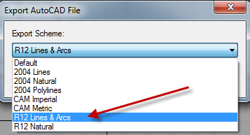
Select the “R12 Lines & Arcs” option and you’re done.
Load the DXF in MeshCAM
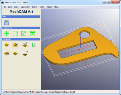
Click “File” then “Open 2D DXF” and load the file saved above. The file will be opened like any other 3D file with the exception of the new “Extrude” window:
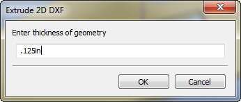
The setting entered here will tell MeshCAM how thinck to make the new geometry. If you’re just trying to cut flat stock then you should make the distance equal to the thickness of your stock. For the example here, we’ll use .125”.
It’s worth noting that this extrude command was added in MeshCAM V4. V3 users will not have this command available.
Define Stock
The stock in MeshCAM is used to define the area in which the tool is allowed to move. By default it is set to the size of the geometry you load (you can see it as the white box around the part). In this case, the stock is touching the geometry so the tool would not be able to move completely around the part to cut it out. We’ll enlarge the stock using the “CAM->Define Stock” command.
Since we just need to add a little room around the part, enter “.2” for the “Right” and “Back” values under the “XY Position” area. All other defaults are fine.
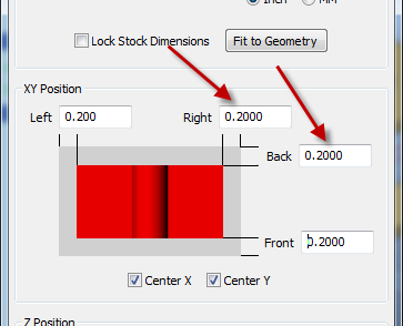
In the screenshot below, you can see that the white box representing the stock has been enlarged.
Add Supports
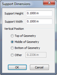
The current settings would be fine if you’re going to hold the stock down with double-side tape or something similar. What if you need to add tabs or other supports to hold the parts in place for machining? Use the “CAM->Set Geometry Supports” command and enter the settings below:
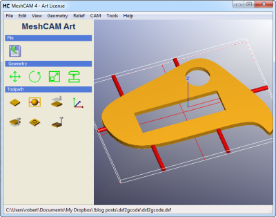
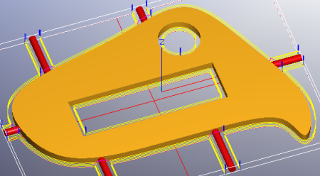
Click at a few spots around the part to automatically place supports. Don’t worry if you get one or two of them wrong, you can right-click to remove the last support. When you’re done it will look something like this:
Generate a Toolpath
The only part left is the toolpath, and there’s not much to that. Since we’re just looking to cut out a profile, we can skip the normal roughing and parallel finishing passes. We’re going to use the waterline and pencil finishing only. As a quick refresher on those two, waterline makes a series of profile passes around the part, each a little deeper than the last. The only thing it does not do it attempt to find the “final depth” of the part to take a last cutout pass. The pencil toolpath is used to trace the outline of the part one file time a full depth and ensure that nothing remains around the part.
We’ll use a .125” endmill for both toolpaths and a stepdown of .03” for the waterline pass. The rest of the settings can be seen below:
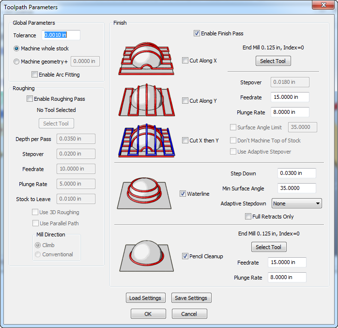
Click “OK” and after a couple of seconds you’ll have a toolpath ready to go:
Way Faster than 2D
After you do this the first time, I think you’ll be agree that this is “way faster” than a traditional 2D CAM program that requires you to select vectors to cut or one that just does a straight DXF to g code conversion where no tool offsets are calculated.
Other Options
A couple of other options for advanced users:
1) If you want to plunge to full depth and cut the whole thing in one pass then skip the waterline and use only a pencil pass.
2) You can tell MeshCAM that the waterline tool is a little bigger than it really is. This will cause it to offset the tool more than it should leave a little extra material around the part. This lets the pencil pass cleanup the final surface in a single pass with a better finish. For example, if you tell the waterline pass that your .125” endmill is actually .135”, MeshCAM will leave .005” for final cleanup. This is one way that lying to MeshCAM can get you additional features that were never programmed into it. Don’t worry, it’ll forgive you.