Undercuts are something that every machinist, CNC or otherwise, will eventually have to deal with. There are a couple of ways to deal with them but I have a definite favorite that might be a good trick to take a look at.
What is an Undercut
An undercut is an area of a model where one part overhangs another part, creating a void in the middle that cannot be reached by a traditional 3-axis mill or router. That probably sounds like gibberish so here’s a picture-
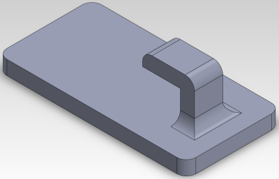
That “hook” creates an area between it and the back plate that cannot be machined. You’d have to leave a section unmachined or break it into multiple parts and bolt or glue it together.
It’s worth noting that an “undercut” is specific to a direction of machining. The part above only has an undercut if you machine it from the top or the back. You could flip it on it’s side to machine it but that’s not really a cure all- I could easily come up with a part where that is not possible. We’re using a simple part here to illustrate a point.
Special Tools
Special tools are sometimes used to machine simple undercuts. These are sometimes called “slot cutters” or “lollipop cutters” depending on their shape. Both tools feature a tip that is wider than the shaft. This gives the machinist some limited ability to reach into the undercut- but only by the difference between the tip and shaft diameter. For many uses this will be fine but it is certainly not a universal solution.
A big negative for these tools is that most CAM software does not support them directly. Because these special cutters are infrequently used, only the high-end CAM programs include algorithms that can utilize them. For the rest of us, special cutters require manual gcode, tricking the CAM program, or moving the mill manually. I’ve never had a case where their use outweighed their negatives.
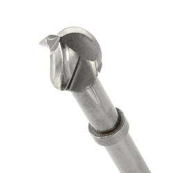
It’s easy to see that the cutter above may not have the reach to machine the whole undercut in our example part. Surely there’s another way…
Think Like a Plastics Engineer
I spent years as an electrical engineer working with factories in China, ignoring the plastic and mechanical parts of my projects. One day a friend of mine showed me how he modified a part to eliminate a small undercut that would cause excessive wear in one of our molds. It was a common practice for plastic injection molding but it was not something that ever occurred to me- cut a hole in the back of the part for a tool to get in. In retrospect it was obvious but it wasn’t something I ever spent much time thinking about.
![]()
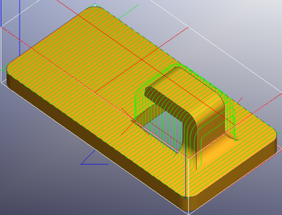
This access hole in the back of the part allows you to flip the part over and machine the undercut from the back. MeshCAM has a built-in “two-side job” type that makes this really easy. Below is what the front and back toolpaths might look like:
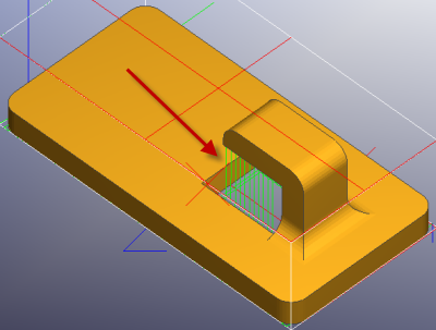
The red arrow shows where the tool is now able to access the undercut and remove that material.
A More Complicated Part
The same technique above can be applied to more complicated parts that would be much more difficult to machine in their “standard” configuration. Here’s one one of those, half a hinge:
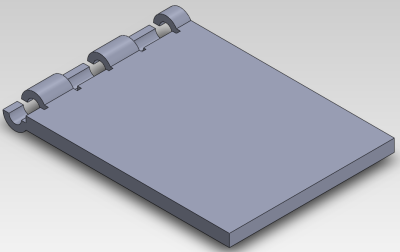
The hinge is now easy to machine from two sides and would be easy to mold if necessary without slides or inserts. It’s not exactly going to work for a restoration job on an antique piece of furniture but it’s still a cool trick.
Play with Toys
If you have kids then you’re probably going through toys at a rapid pace, try opening a few up and looking at how they are designed. You will likely be shocked at the number of shortcut and tricks used to make complicated mechanisms that can be produced in simple injection molds without undercuts. Most of these injection molding tricks are applicable to the milling process as well.
Not a Cure for Every Case
Cutting a hole in a part is not going to work every time but it does work more often than you think and it’s one of the easiest ways to machine a difficult part.