Building Guitars with MeshCAM
By John Williams
Introduction
I started building guitars as a hobby in 1997 after a challenge from Jim Grainger, a great friend and great luthier. Jim, the owner of Custom Fretted Instruments in Sparta, Tennessee, told me that the best way to learn how to build a guitar is to build a guitar. Over the years we have had many discussions concerning how to build a guitar more precisely and efficiently, and a few years back the discussion turned to CNC. In 2003, I started the search to learn more about CNC, and, not being a trained machinist or computer programmer, the learning has been slow and tedious, yet extremely rewarding.
I built my first CNC router with plans and a kit I bought from www.HobbyCNC.com in 2004. I modified the original design over the next two years, upgrading both the router from a standard Dremel to a more powerful Dremel Advantage router. I chose the Advantage because it could hold a ?" bit and its speed is adjustable up to 30,000 RPM.
My control software is TurboCNC 4.01 available from www.dakeng.com, and it is a great program. I am using a 1999 vintage Toshiba laptop with a 4 gig hard drive and Windows 98 SE to run the software in DOS mode..yes, DOS mode. I had to remember all of my old DOS commands!
Using relatively small stepper motors (about 85 oz/in), I was able to cut out my first guitar body with the CNC router in May 2006. The body was relatively easy because it was generally what is known as a "2 ? D" cut rather than a full 3D, or three dimensional cut. The guitar body had straight cuts and there were no complex curves. Figure 1 shows the router in action cutting out a guitar body. Nothing fancy here - this is a utilitarian device! Think of it as a "proof of concept" machine.
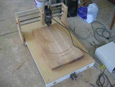
Figure 1. The first CNC body
However, to fully realize the potential of CNC, I would have to figure out how to cut a guitar neck, with its graceful, curving surfaces. This is the story of how I figured it out the hard way. In short, this is a $200 guitar neck with about $100,000 in labor costs thrown in for free!
Measuring and Drawing
Using several of my favorite Fender-style guitar necks as patterns, I drew the original outline of the neck and headstock in CorelDraw. Measuring the width of the heel and nut of the neck very precisely was of great concern because these two cuts would affect everything about the neck. I originally started with cutting the billet in 2D so I could manually shape the neck if I chose, and it seemed a pretty practical way to do it. The difficult part was getting the neck's heel right (Note: The heel is the part of the neck closest to the guitar's body). I used a separate cutting file for the heel to allow me to re-zero the router and get a precise cut. This also allows me to create either a Strat-like smooth contour or a more square Tele-like curve.
Using a graphics program known as Rhino 3D, I drew the three dimensional neck profile. First, I had to figure out how to use Rhino 3D! Never underestimate how long it will take you to figure out the right way to draw a neck in a computer aided design (CAD) program. The difficult part was to determine the proper diameter and "curviness" of the back of the neck to make the neck playable. I used a number of contour gauges to get the curve of the neck on to paper then I scanned them into Rhino. Once in Rhino, I traced them and drew the neck's profile. The actual neck profile only consists of two curves - one at the heel of the neck, and the other directly behind the nut near the headstock. These are easily modified to make a thicker or thinner neck, based on the guitarist's preference. Figure 2 shows the 3D model of the surface in Rhino 3D.
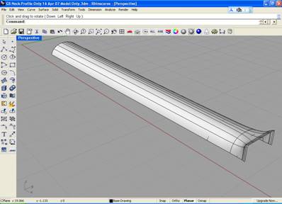
Figure 2. Screen Shot from Rhino3D
Converting the Drawing
Drawing the neck in Rhino was only the first step. I exported the Rhino model as a stereo lithography, or *.STL file. Using a program called MeshCAM, I converted the Rhino drawing into a tool path. Figure 3 on the next page shows the model in MeshCAM.
I found MeshCAM from a post on the www.cnczone.com forum. I had never used a computer aided manufacturing (CAM) program before, but I found MeshCAM to be very intuitive. This lead to a great deal of experimentation because I couldn't find anyone who would admit to having carved a guitar neck with CNC, even though I knew they were out there. There is a taboo among many builders that using CNC cheapens their art. I'll let you be the judge.
To get to a finished product, I cut a number of iterations of the neck in poplar, even though the final neck would be in maple. I got the ?" thick poplar blanks at Home Depot, and I cut about twenty of them before I got the cut right. I burned the really ugly ones in my outdoor fireplace - leave no evidence! In addition, I went through several iterations of router bits and end mills. I finally settled on some ?" carbide end mills - both square and round nose -- available through a store on eBay. They did a great job cutting through the poplar and the maple.
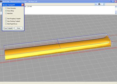
Figure 3. Screen Shot from MeshCAM
There were three issues I had to fix. First, I had to reliably find the 0,0 position on the router that corresponded to the file. I fixed this by attaching the neck billet to an MDF template, which is explained later. Second, there was a question as to how much roughing with a square endmill I should do, and the tradeoff in milling time. Third, I had to decide on how much fine milling with a round nose endmill I should do, and, again, what was the tradeoff in milling time. Finally, I had to find the right combination of router RPM to feed rate of the router. Too fast and the router would bog down and stall; too slow, the wood would burn along the edges.
MeshCAM allows you to specify the roughing and finishing passes. For my final neck, I chose the following as a good compromise between a nearly finished neck and hours of milling. Figure 4 shows how I set-up the parameters.
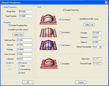
Figure 4. Parameters page from MeshCAM
Once the parameters are set, you can view the toolpaths in MeshCAM. Figure 5 shows the tool paths overlaid on the neck model.
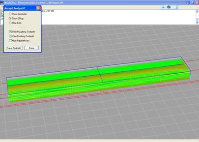
Figure 5. Toolpaths from MeshCAM
Cutting the Part
Step 1. I got the maple billet from www.warmoth.com. It was very clear maple and extremely hard. I attached the billet to the MDF template from the bottom using two 1" drywall screws. The screw holes will be routed away later in the process. The template is indexed to the bed of the router using two ?" dowel plugs. This is the only way to ensure consistent alignment.
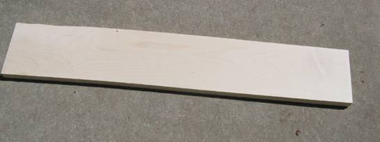
Figure 6. The maple billet!
I used two Quick-Grip clamps on each end of the router to secure the billet and the MDF template to the router. I like those clamps because they are particularly easy to use, even with one hand.
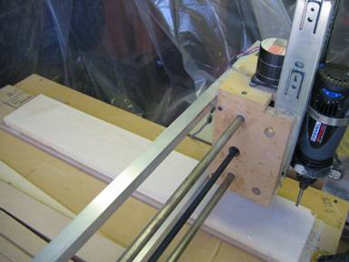
Figure 7. Template and billet mounted on the router's bed
Step 2. After much trial and error I decided on a proper 0,0 position on the router. I used a digital caliper to measure the position of the X and Y axis in relation to the end of the router bed. After using various methods, this is the only one I can say is consistent.
Figure 8 on the neck page shows the router cutting out the 2D neck slug from the billet. I used a ?" diameter carbide endmill to complete the cuts. This procedure produces an outline of the neck and the rough tuner holes.
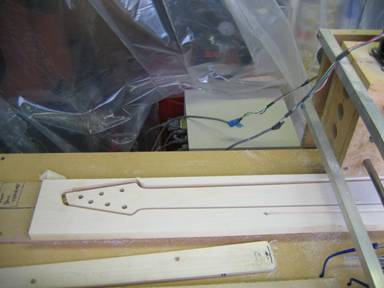
Figure 8. Routing the 2D neck blank
Figure 9 below shows the 2D blank still attached to the MDF template. The outside of the maple billet has been removed. It is important to note that if the billet is not long enough to be held by the clamps at the end of the router bed, you must use either screws or carpet tape to keep the outside of the billet in place. As you can see in Figure 8, once the routing is complete, the outside of the billet, i.e. the part of the maple not attached to the neck, will be free to move around.
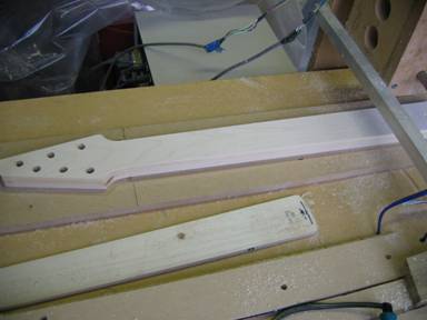
Figure 9. Neck blank, nearly ready for 3D routing
Step 3. Once the outside, or waste maple was removed as shown in Figure 9, it was time to route the neck heel. This is the part of the neck which fits into the neck pocket, and its precision is mandatory. At this point I reindex the machine to 0,0 and cut the neck heel using the same ?" square endmill.
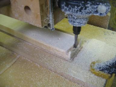
Figure 10. Cutting the neck heel
Step 4. Once the neck heel was complete, I loaded the 3d cutting file generated by MeshCAM. Using the same ?" square end mill, I ran the roughing pass on the neck. Figure 11 shows the stair-stepping cuts of the roughing file generated by MeshCAM.
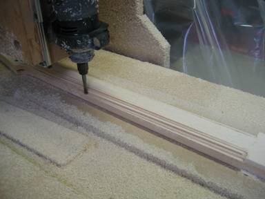
Figure 11. Roughing pass, back of the neck
Step 5. Once the roughing pass was complete, it was time to finish the back of the neck. I changed the bits, installing a ?" diameter round nose carbide end mill. When the router's Z axis was reset to 0, I resumed the routing for the finishing pass. Figure 12 shows the finish pass in progress.
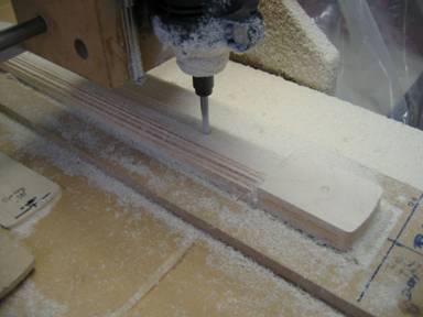
Figure 12. Finish pass, back of neck
Once the finishing pass was complete, I took the neck off of the MDF template. All routing on the back of the neck was complete at this point. Figure 13 shows the neck ready for the next series of cuts.
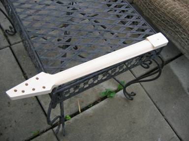
Figure 13. Back of neck.mission complete
Step 6. I flipped the neck over and attached it to the front template. Using the same ?" dowel indexers, I attached the template and the neck to the router bed. The next cut s would be for the headstock. Figure 14 shows the template and the neck secured to the router.
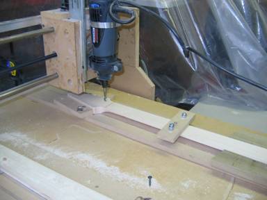
Figure 14. Ready for the next series of cuts
Step 7. Using the same round bit, I routed the headstock. The headstock slopes downward from the bottom of the headstock (see the line in Figure 15) toward the tip of the headstock. It is generally flat from where the tuner holes start to the tip of the headstock. Remember that the tuner holes were drilled from the back. The neck is secured in the template with the crossbar at mid-neck and several bolt hold-downs at the heel of the neck.
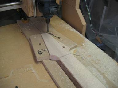
Figure 15. Routing the headstock
Step 8. Once the hold downs were moved, I changed back to the ?" square nose bit to route the trussrod channel. The cross bar hold down is moved to a fixture at the headstock, leaving the middle of the neck free for routing.
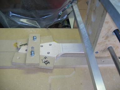
Figure 16. Neck secured in the template
Once the neck and the bit were secure, I started the routing on the trussrod channel. I normally use a Stew-Mac Hot Rod, available from www.stewmac.com. They have specific instructions on their website for routing channels specific to this trussrod.
Figure 17 shows the routing process beginning, and also shows the hold downs at the heel of the neck. The bolts do not go through the neck; rather, they ride along side and allow the nuts to hold the billet down.
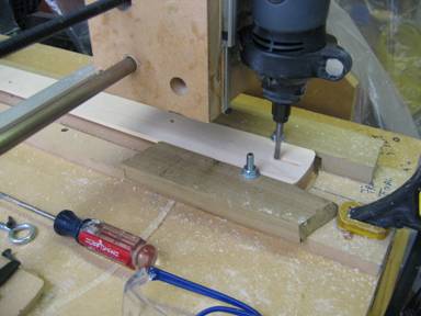
Figure 17. Routing the trussrod channel
Figure 18 shows the completed trussrod channel and the two index holes for the fingerboard.
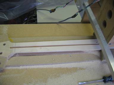
Figure 18. Trussrod channel complete
Step 9. Once the maple portion of the neck was nearly complete, I turned my attention to the fingerboard. I got the rosewood fingerboard from www.stewmac.com. It has a 25 ?" scale and comes as a rectangular billet with the fret slots already cut. This is an operation I could do with my router, but the slots are very precise on this fingerboard and the cost above an "uncut" board was not prohibitive. The board had to be cut to match the profile of the neck, so I attached the fingerboard blank to the MDF template with carpet tape. Using the same straight ?" endmill, I routed the outside profile. Once the profile was completed, I drilled the ten ?" holes for the dots with another file as shown in Figure 20 on the next page.
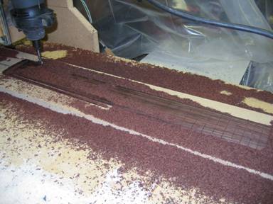
Figure 19. Cutting out the fingerboard
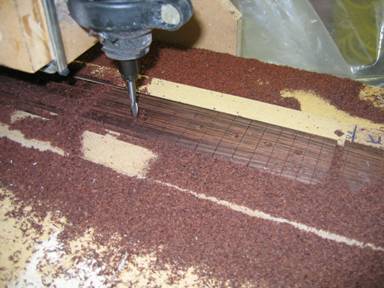
Figure 20. Drilling holes for fingerboard dots
Step 10. After completing the fingerboard, I installed the trussrod in the neck blank. The trussrod drops into the slot, and I secured it with several squirts of silicon tub caulking. This keeps the trussrod from moving in the slot, and keeps it from vibrating at high volumes!
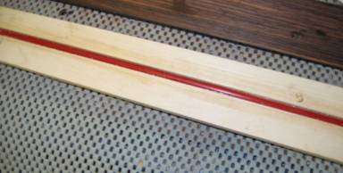
Figure 21. Installation of the trussrod
Step 11. I released the fingerboard blank and drilled two alignment holes in the bottom of the fingerboard to match those on the neck blank. Figure 22 on the next page shows the holes with dowels in the maple neck which will align during gluing.
I made a MDF jig for drilling the holes into the rosewood fingerboard. This is a critical maneuver because if the holes are too deep, they may come out the top of the fingerboard, ruining a great piece of wood. If they are too shallow the alignment pins will not fit during gluing. I always recommend practicing placing the fingerboard into position prior to gluing.
Gluing a fingerboard onto a neck is critical, and if the fingerboard slips while the glue dries, it is nearly impossible to salvage the neck.. I know this from experience.
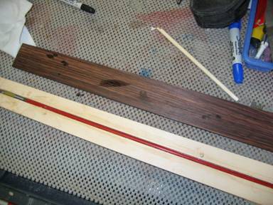
Figure 22. Fingerboard and neck index marks
Step 12. When the silicon sealer was dry, I glued the fingerboard on the neck blank. I used masking tape to cover the trussrod, and then applied Titebond glue. While the glue was tacky, I pulled the tape off and placed the fingerboard on the neck. The tape keeps glue from getting into the trussrod cavity and potentially keeping the trussrod from working properly. Again, the pins assured the alignment of the neck and fingerboard. Use plenty of clamps to clamp the fingerboard down, and use regular waxed paper between the fingerboard and clamps to keep the clamps and cauls from sticking to the fingerboard.
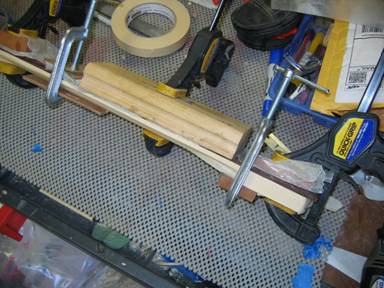
Figure 23. Gluing the fingerboard to the neck
Step 13. When the glue was dry, I sanded the fingerboard even with neck blank. This makes a very nice edge and ensures that the glue joint is not visible on the finished neck.
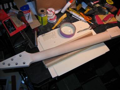
Figure 24. Neck with fingerboard attached
Step 14. Once the fingerboard was sanded flush with the sides, I used a straight cabinet scraper to smooth the back of neck and remove machining marks. I finished it up with some 220 grit 3m Sandblaster sandpaper. Yes, there is a difference in sandpapers, and I've found the Sandblaster papers to be superior to the other "Home Depot" brands.
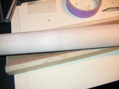
Figure 25. Neck after smoothing with cabinet scraper
Step 15. Once the back of the neck was complete, I sanded the front of headstock. I started with the cabinet scraper and finished with the 220 grit paper. Note: I never put any sandpaper more aggressive than 220 on the guitar. I've found the sanding marks just too hard to get out of softer woods.
By the way - this is an original headstock design. Be on the lookout for counterfeiters/cheaters!
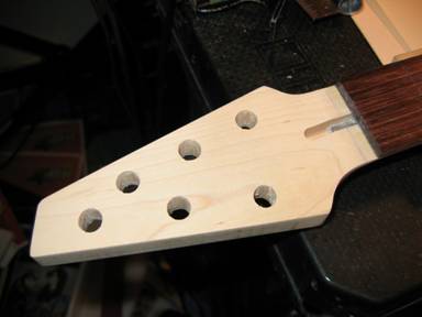
Figure 26. Headstock after smoothing with cabinet scraper
Step 16. Next I installed ?" Mother of Pearl (MOP) dots in the fingerboard with Titebond glue. They slid right in to the holes and fit perfectly. Once the glue was dry, I sanded the dots flush with Sandblaster paper on a 12" radius sanding block as shown in Figure 28 on the next page.
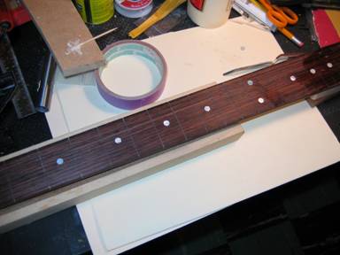
Figure 27. Mother of Pearl dots glued into fingerboard
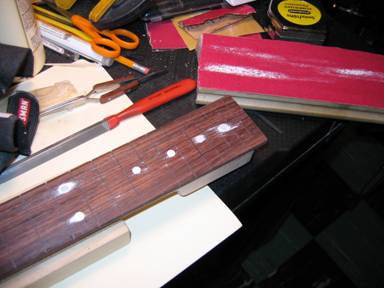
Figure 28. Leveling the Mother of Pearl dots
Step 17. Next, I installed the side dots. I measured their positions and used a sharp awl to mark their positions. Using a hand drill, I drilled out the holes. I super glued the material into the holes, then trimmed them flush with a razor blade.
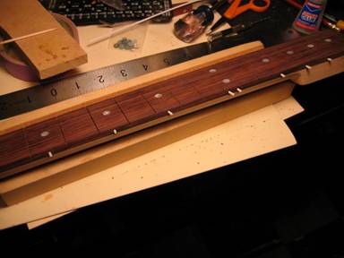
Figure 29. Installing the side dots
Step 18. The neck step is a technique I use and I recommend it to all builders. Using a lint free cloth, I rubbed two coats of Zinnsser SealCoat shellac onto the neck and the side of the fingerboard. Do not shellac the playing surface of the fingerboard - it will remain unfinished!
The shellac will protect the neck during the fretting and setup process, and it will keep oils and other contaminates from seeping into the wood. Shellac is the wonder finish, and I there is no finish - to my knowledge - that will not stick to it. It is a great sealer for nitrocellulose lacquer, which I will use on this neck.
Next I installed the fret wire. I normally press my frets in, but I've been using the fretting hammer a great deal lately. I was feeling a little adventurous, so I hammered the frets into this neck.. This takes some getting used to, so I recommend practicing on scrap prior to going final. It is difficult to overcome a bent or poorly seated fret. Take your time here. There are a number of good books on this subject available from www.stewmac.com.
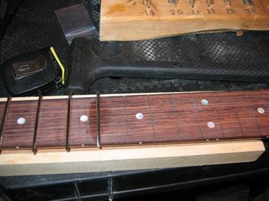
Figure 30. Installing the frets
Step 19. After installing the frets and filing them flush with the sides of the fingerboard, I installed the tuners. I used a reamer to true the holes to 10mm, and drilled holes for the tuner screws with a 1/16" bit. Make sure you take the time to ensure the tuners are aligned prior to drilling the holes. At this point, I only screwed the screws in about half way just to hold them in place.
Step 20. I aligned the neck on the guitar using a Quick-Grip clamp and two pieces of fishing line. First I clamped the neck to the guitar and "eye balled" the alignment. You will find there is quite a bit of movement possible with the neck. Next, I taped the fishing line in the position of the low and high E strings, and ran them from the headstock to the bridge on the body. Using these two surrogate guitar strings, I moved the neck slightly back and forth until it was aligned.
After being sure of the alignment, I drilled the four attachment holes on the heel of the neck with a 1/8" bit. These four screws attach the neck to the body, and I used the holes in the body as a template. I used a 7/16" bit pushed through the holes in the body to mark where to drill on the neck. I then unclamped the neck and drilled the holes. Make sure you don't go to deep, or the drill bit will poke through the top of the neck!
Once the neck was on the guitar, I strung it up and make a nut. Again, this is a potentially tedious task. The fretting book from Stewart-MacDonald has a good primer on this, as does their website. Look under "Free Information" and there is a good photo run down of the process. Figure 31 shows the neck on the guitar with the strings tuned to pitch.
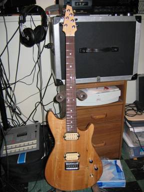
Figure 31. The guitar with the new neck installed
Step 21. Once the neck was on the guitar for a day, I completed a fret job. I let the strings sit on the guitar to get it used to the pressure, and it really does make a difference in the fret job. Do not glue in nut yet! The reason I do the fret job at this point to avoid having to fix a problem when that beautiful finish is already on the neck! Figure 32 on the next page shows the new neck on the guitar in the neck jig. In my opinion, this is best way to ensure that you are getting a good fret job. Again, this device is available from www.stewmac.com.
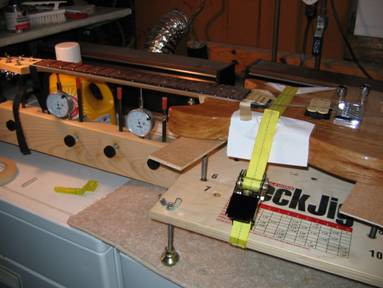
Figure 32. Fret job with the Erlewine Neck Jig
Step 22. Once I played the guitar and I was satisfied with the fret job, I masked the fingerboard, removed the tuners, and applied a nitro lacquer finish.
The Guitar ReRanch, which can be found at www.reranch.com, has a great section on how to complete finishing on guitars. I did nothing special on this neck, and I finished it with MinWax Classic Gloss Lacquer, which is available in spray cans from Home Depot.
Once the finish had dried three days, I applied the decal. Figure 33 shows the process of figuring out where the decal will fit. I made the decal from laser decal paper from www.micromark.com. I think it turned out great.
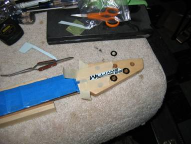
Figure 33. Where should the decal go?
Step 23. I let the finish dry for a week and wet sanded it with 400 through 2000 grit papers just like they talk about at the ReRanch.
Once complete, I buffed on my pedestal buffer.
Step 24. I let the freshly buffed neck sit overnight and reinstalled the tuners. I removed the tape, removed the residue with lighter fluid (naphtha), and buffed the frets with a Dremel tool. I particularly like Mother's Billet Metal polish for polishing frets. You can normally find it at Wal-Mart or an auto parts store.
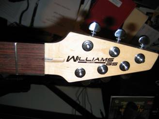
Figure 34. Headstock complete without nut
Step 25. I reinstalled the neck on the guitar and strung it up. I checked the nut again before gluing, and once I was satisfied with the fit and finish, glued it in place with Titebond.
I used a small Quick-Grip to hold the nut in place while the glue dried. While the glue was drying, I oiled the rosewood fingerboard with some Formby's Lemon Oil from Lowe's. It keeps the wood supple and looking great. Don't use too much - a little goes a long way.
Step 26. Once the glue was dry, I tuned the strings to pitch, plugged in the guitar, and rocked!
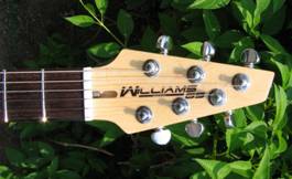
Figure 35. The finished guitar!
Conclusion
As you can see, there is still a great deal of hand finishing required when using CNC to build guitar necks. However, in the final analysis, using CNC to make a neck improved my building in two areas: precision and repeatability. It does save time because now I can work on other tasks while the router labors away at carving. While there is still a great deal of manual labor involved in making a neck, but there is clearly less than starting from scratch.
Next, you have to have MeshCAM for 3D routing. Using 2D files drawn with CorelDraw are fine for a number of tasks, but to really open up the potential of your CNC router, you have to go to 3D, and MeshCAM is a wonderful software tool no matter your experience level.
Finally, it is harder than it looks. You will have to log some serious hours to get the product you desire. Remember - the price of low precision is failure! Draw it correctly from the start!
Check out my website at www.guitarattack.com for more information. Now I can make as many necks as I want.to earn back that $100,000 in labor.