One of the fundamental parameters of any CNC machining, and 3D machining in particular, is the stepover. It is not a stretch to say that it is the single most important parameter in determining the quality of the finished parts you will produce. A machinist can pick a value by feel, based on previous experience, or do the math and calculate the exact value that will give them the finish required. New users generally don’t have the experience and don’t know the math so it takes a while to get an intuitive understanding of of the stepover parameter.
The following post focuses mostly on 3D toolpaths so we’ll be assuming the use of a ball mill. Once you understand the basic concepts it’s easy to apply them to flat end mills and bull mills. We’ll try to build to some rules of thumb rather than derive equations that most users won’t be interested in.
Definition of Stepover
Almost all CNC toolpaths are based on the concept of one toolpath being offset from another by some distance; this offset distance is generally called the stepover. Most CAM software, MeshCAM included, uses a couple toolpath styles in particular with these offsets- the raster toolpath (sometimes called a zig-zag toolpath) and a contour offset.

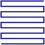
Adjacent sections of the toolpaths above are separated by the stepover value chosen by the user.
Scalloping
The pictures above show how a toolpath is arranged from above but a side view clearly shows the primary side effect of your stepover choice- scalloping.

The area in red is the part of the stock leftover on the part in between the toolpath offsets. It’s important to understand that these are not good; they are not in the CAD and may need to be removed after machining by sanding or polishing. CNC machinists are almost always trying to reduce the scalloping as much as possible and many man-years of effort have been spent trying to develop toolpath algorithms that minimize them.
Scallop vs. Stepover
A moment spent looking at the image above illustrates at connection between scallop height and the stepover value- increase one and the other increases as well. In the images below we’ll use a stepover equal to 1/10, 1/5, and 1/3 of the tool diameter to show this correlation. To put real numbers on this, that would be equavalent to a .012, .025, and .042” stepover for a .125” ball mill.


As you can see, the change in quality is so dramatic that you might be tempted to always use the smallest stepover possible.
Speed vs Quality
It shouldn’t be surprising that you’ll have to give something up if you want to use a really small stepover. In this case you’ll trade time for quality- you give up machining speed to use a small stepover or give up quality if you want a quick machining time. This is easy to understand when you consider that the total length of a toolpath will approximately double if you cut the stepover in half. The question is, “Will cutting the stepover in half double the quality of my part?”
The Sweet Spot
It turns out that there is a point of diminishing returns in the time/quality tradeoff. Below is a graph of scallop height vs stepover that illustrates the effect. The graph has been normalized to a tool diameter of 1.0 so it’s easy to scale it to any tool you happen to be using. (Click on it to see a bigger version)
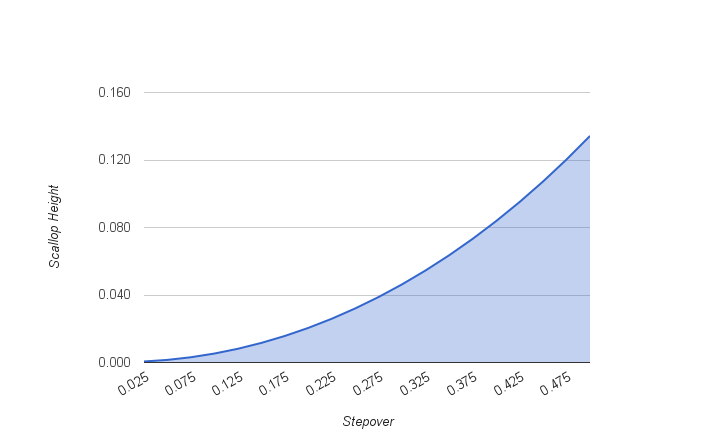
The important thing to note is the shape of the graph- it tends to flatten out when the stepover goes below about one eighth of the diameter. This means that when you go below this point you’re going to take more time to machine without a proportional gain in finish quality. If you’re machining a steel injection mold then it may still be worth it but you really need to be sure before doing that.
Scallop vs. Tool Diameter
Here’s the other thing we can glean from the math behind the chart above- for a given stepover, a larger tool will give you a smaller scallop. This means that you can get a better finish “for free” if you can use a larger tool. Obviously, this only works if a bigger tool will fit into all of the parts of your geometry but this is one of the few “win-win” things we can do get better results if it does work for your geometry.


Keep the Material in Mind
Before you figure out what stepover you need to get a .0001” scallop, think about what you are going to machine- wood, tooling board, aluminum, steel, etc. I can tell you that in many cases you can do 10 minutes of sanding on a wood part to get a finish that would have taken you an extra hour or two to get straight from the mill. Likewise, tooling board like Renshape can be hand finished quickly enough that it may not be worth doubling the machining time to get a better finish. If you’re cutting steel or other hard materials then it’s probably worth letting the mill do more of the hard work.
The second characteristic of the material to consider is what kind of detail it can hold. MDF will not hold features in the .01” range but metal will. If your material cannot hold a detail that is smaller than your scallop height then you do not need to reduce the stepover; doing so will only waste your time without producing a better finish.
Keep the CNC Machine in Mind
It may be a poor craftsman that blames his tools but we do have to be realistic about the nature of our equipment. In particular, how long do you trust your mill or router to run trouble-free? I started out with a small table-top mill that, while very good, could not be trusted to run for hours without missing a step or hiccuping in some way that gouged a part I had waited half a day to get. If you have a machine like this then it’s worth thinking about the picking the maximum stepover based more on machining time than finish.
Rules of Thumb
That was a nice bunch of pictures but you may still be left with the question, “So what stepover do I use?” Here are a few suggestions:
- The stepover should be between 1/3 and 1/10 of the tool diameter
- Use a larger stepover, in the 1/5 to 1/3 range, for soft materials that cannot hold detail well
- Use a smaller stepover, in the 1/5 to 1/10 range, for hard materials or materials that can hold significant detail like metal and jewelers wax
- Use the largest tool that will allow you to machine your geometry
Once you have a few projects complete you can adjust the guidelines above to suit you materials and machine.